General Diagnostic Considerations#
\[\]First, let us categorize some broad categories of items to consider when we think about plasma diagnostics by asking a few questions:
Which plasma properties do we want to measure?
- Densities for individual species, velocity, temperature (moment measurements). In the case where a plasma is not thermal (Maxwellian), we may need to measure species distribution function \( f_s (\vec v) \)
- Plasma content, i.e. species concentrations, \( Z_{eff} \) (which is a determining factor in resistivity and radiation power)
- Plasma currents, current densities, electromagnetic fields. Note: some properties are inferred from other properties, e.g. \[\vec j = \sum_s q_s n_s \vec v_s = \frac{1}{\mu_0} \curl \vec B \quad \text{if} \quad \tau \gg L/c\] \[\div \vec E = \frac{1}{\epsilon_0} \sum_s q_s n_s\]
- Global measurements: input power, radiative power, energy confinement time, thrust, fusion reaction rate/yield.
What spatial resolution is needed?
- Some plasma diagnostics are spatially integrated, and some are chord-integrated, single-point measurements, 1D spatial resolution \( f(r) \), 2D \( f(r, z) \), 3D \( f(x, y, z) \), and 6D \( f(\vec x, \vec v) \)
- How many points in space are sufficient to resolve? 4, 10, 1000…
- Typically, “spatially-resolved” means a measurement at a particular location (not volume-integrated or chord-integrated).
What temporal resolution is needed?
- Time-integrated over pulse, once/twice during a pulse, gate time (how long is the shutter open?), continuous acquisition, sample rate and bandwidth
- “Temporally-resolved” includes all these except time-integrated measurements
What other things do we need to take into consideration?
- Does measurement require plasma access? Ports are usually small and expensive. What if the plasma is contained in a flux conserver, and what if the ports are far from the plasma? Some diagnostics require multiple ports and may be constrained to be coaxial (laser diagnostics) or orthogonal (scattering measurements).
- Data analysis: Many properties are inferred from measurements indirectly, data has to be processed to extract plasma properties. Analysis/processing often applies assumptions which can increase the uncertainty of the measurement.
- Suitability of detectors, lasers, and circuitry of detector itself. Often introduce sample rate, resolution, uncertainty limitations.
- Signal noise from detector and cabling
- Plasma reproducibility, shot-to-shot variability
The limitations and challenges with making experimental measurements of plasmas can be compensated by computational modeling, which have different, and often complementary, limitations. NIF is a good example: each pulse has a dedicated set of simulations for how much energy is deposited, how the target implodes, etc. Measurements (neutron yield, X-ray measurements, etc.) are compared with computational models to find agreement and to understand what happened in the experiment itself.
Types of Plasma Diagnostics#
Passive Diagnostics#
Passive diagnostics do not interact with the plasma and are non-perturbative. Self-emission spectroscopy, imaging, and X-ray and neutron detectors are examples.
Active Diagnostics#
Active diagnostics are external means to interact with the plasma and measure its response. These are further divided by the extent of perturbation. For an example, laser scattering at lower power often doesn’t change the plasma properties appreciably, but Thompson scattering can require high enough power to significantly perturb the plasma.
Safety Concerns#
There are three main safety concerns when performing plasma experiments and diagnostics:
- High Voltage. We often plasmas by applying a high voltage to a neutral gas. Many diagnostics use high voltages, be it applied to detectors or in laser systems. Technically voltages as low as 30V can be lethal under the wrong circumstances.
- Lasers. Visible and infrared like \( CO_2 \) and \( YAG \). Classified by power level and frequency. Class 4 \( Nd:YAG \) and \( HeNe \) are commonly used in the lab.
- UV Light. Plasmas emit in broadband (Bremsstrahlung and line radiation mostly), including UV radiation (100nm - 400nm). Can cause “sun burns” and retina damage (“snow blindness”). Most things will block UV light, but often we want the UV radiation for diagnostics and use fused silica windows which transmit UV light. Calibration light/lamps also emit UV radiation.
Noise and Signal Contamination#
Many continuous time-resolved diagnostics use detector transducers, sensors, located near the plasma to produce an electrical signal. The signal is recorded by an oscilloscope or digitizer in this sort of setup:
(Missing diagram)
Plasmas are often formed through electrical discharges or RF waves, the plasmas often produce large electric fields, currents, and magnetic fields, sometimes with high fluctuation frequencies. How do we measure the plasma properties without contaminating the signals with noise, which is any unwanted signal that couples to the detector circuit.
Plasma diagnostics are susceptible to two primary types of noise:
- Electrostatic - typically generated through capacitive coupling
- (Electro)magnetic - comes about from inductive coupling
Capacitive Coupling#
Proximity of sensor to plasma generates electrostatic current \( I_{es} \) through capacitive coupling.
(Missing diagram)
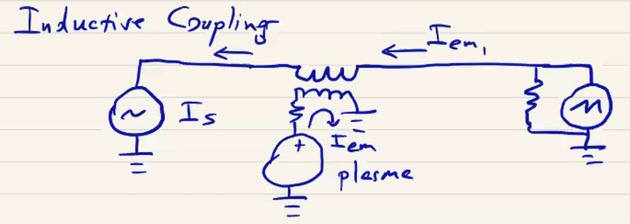
Inductive Coupling#
Inductive coupling, as the name implies, operates through the inductive principle. It can occur as a result of ground loops which can be of a large area.
\[\dot \Phi = \int \pdv{\vec B}{t} \cdot \dd \vec s = - \oint \vec E \cdot \dd l = - V_{emf}\]Since the loop includes the entire setup, even a low \( B \) can produce large \( V_{emf} \), which is across the oscilloscope we’re reading. Now the plasma produces a magnetic field which couples to the detector circuit. The magnetic field generated by the plasma effectively acts as a transformer which produces a current in the measurement circuit. In contrast to capacitive coupling, with inductive coupling the \( I_{em} \) current doesn’t have an alternate path, so must be same magnitude across the whole circuit. We can use these kinds of features to deduce the kind of noise being generated.
Minimizing Noise#
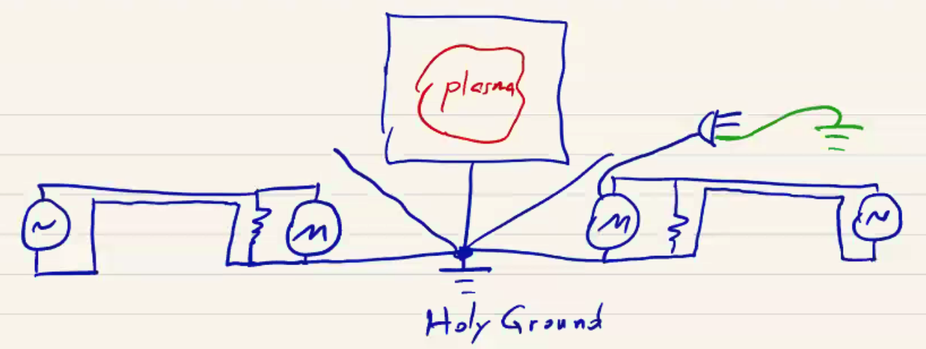
Minimization of noise requires careful consideration of grounding and shielding.
- Single-point “star” grounding. Connecting all devices to a single ground point (“holy ground”) can eliminate ground loop and prevent ground currents
Minimize loop areas of signal cables and detectors by using twisted-pair wire or coaxial cables.
Magnetic shielding: Enclose detectors in mu-metal (high-permeability \( \mu \) material), often some sort of \( FeNi \) compound. This shields pulsed magnetic fields (and even static fields, if you can spin the detectors). Sometimes necessary for cameras, photomultiplier tubes, CRT, and other sorts of vacuum electronics where loop area can not be reduced.
Electrostatic shielding: E.g Faraday cage, can reduce capacitive coupling if shield itself is well-grounded. As the plasma creates electric field which charges capacitive coupling, it charges the grounded shield and flows to the star-point ground. Now the capacitive coupling does not drive current through the diagnostic circuit itself.
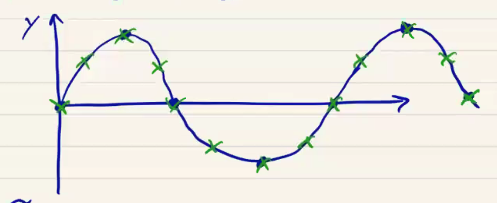
Data Sampling and Errors#
Given a continuous signal \( y(t) \) that is sampled at a fixed rate such that we have \( y_n = y(t_n) \), what is the sufficient sample rate to guarantee loss-less reconstruction of \( y(t) \)? The Nyquist-Shannon sampling theorem states that: If a signal \( y(t) \) contains no frequencies higher than \( B \) Hz, it is completely determined by giving its coordinates at a series of points spaced \( 1/2B \) seconds apart. An equivalent statement to define the bandlimit is “any frequency \( B \), such that \( B < f_x ^N /2 \), where \( f_s ^N \) is the sampling rate for perfect construction.” The threshold established by \( f_s^N/2 \) is called the Nyquist frequency. \( f_s ^N \) is confusingly called the Nyquist rate, and is the rate at which you need to sample the signal.
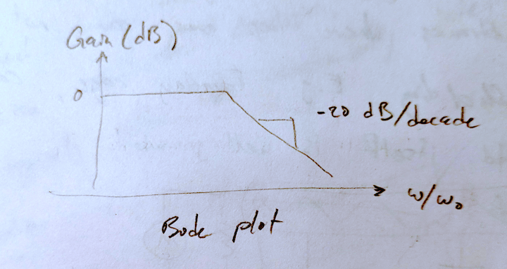
Signal components higher than the Nyquist frequency produce aliasing errors. Features like delta functions and step functions contain all frequencies. How do we prevent these from contaminating our signal, or how do we set the band limit maximum? It can be set by the detector response rate, or the detector circuit, or by introducing a low-pass filter:
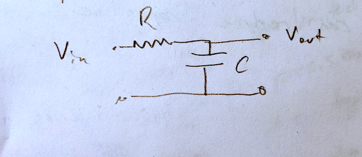
The response (Bode plot) of an RC low pass filter looks like the following, with a cutoff frequency given by \( \omega_0 = \frac{1}{RC} \)
Counting Errors#
When we are counting events (from photomultiplier tubes or spectoscopes, for example), rare events such as photon or neutron events are modeled by a Poisson distribution.
\[P(n) = \frac{m^n e^{-m}}{n!}\]for an event expected to happen \( m \) times on average where \( n \) is the observed event count. \( P(n) \) is the probability of observing \( n \) counts. Earthquakes and flooding are similarly modeled. If you look at the mean value of a Poisson distribution, you get
\[\overline{n} = \sum_n n P(n) = m\]The variance is
\[V(n) = \overline{(m - n)^2} = \sum_n (m - n)^2 P(n) = m\]so \( \sigma = \sqrt{m} \)
When you report the number of counts or observations, you need to include the counting error as \( n = m \pm \sqrt m \), or for large \( n \), \( m \approx n \pm \sqrt n \).
Categories of Plasma Diagnostics#
One may group diagnostics according to the plasma properties being measured. However, this can make diagnostic reporting difficult because many diagnostics measure multiple parameters, or a combination or convolution of various parameters. So instead, we will categorize them according to the plasma phenomenon that the diagnostic exploits:
- Magnetic field
- Electrostatic probes
- Index of refraction
- Self-emission from free electrons (broadband)
- Self-emission from bound electrons (line radiation)
- Laser scattering/interactions
- Neutron measurements
Some basic questions to keep in mind when thinking about how to make a measurement are:
- What is being measured? How is the measured quantity related to the desired plasma property? Which assumptions are necessary to close that relationship? And how do those assumptions affect the confidence in the measurement? How accurate is the measurement?
- What spatial and temporal resolution is needed and provided? For example, index of refraction measurements are chord-integrated, but could be time-resolved or spatially resolved. What are the trade-offs? What is the dynamic range of the measurement?
- How does the diagnostic perturb the plasma?