Index of Refraction Measurements#
The refractive index is defined as the speed of light (in vacuum) over the phase velocity \( n = \frac{c}{v_{\phi}} \), \( v_\phi = \omega / k \). Recall that in vacuum the phase velocity is just the speed of light (\( n = 1 \) in vacuum). In a plasma, we know that the dispersion relation will be substantially different.
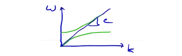
In most materials, \( n > 1 \), but from our crude diagram we can expect plasmas to have \( n < 1 \). \( n \) is related to the plasma density, so laser interferometry can be a technique to measure \( n \).
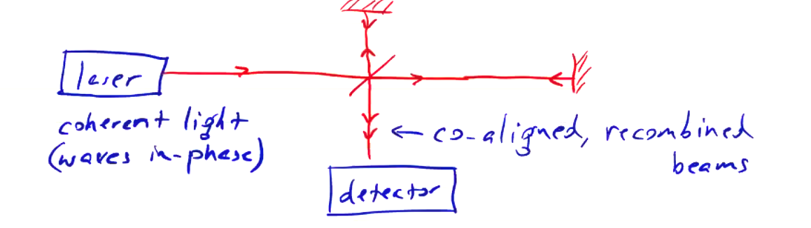
Consider the setup of a Michelson interferometer. A laser source is split by a beam splitter. A portion passes through following path \( L_1 \), reflects from a mirror, and reflects to a detector. Another portion following path \( L_2 \) is reflected to a different mirror, is reflected by a mirror, and passes through to the detector. The co-aligned, recombined beams at the detector is the signal of interest to us. The laser source is convenient because it gives us a coherent light source. If there is a difference in travel time between the two split beams, then there will be a phase difference measured at the detector.
Specifically, the phase shift of each leg is
\[\phi_1 = \int _{L_1} k \dd l \quad (\text{mod}\, 2 \pi) \\ \phi_2 = \int _{L_2} k \dd l \quad (\text{mod}\, 2 \pi) \\ \Delta \phi = \phi_2 - \phi_1\]If we introduce a plasma in the path of path \( L_1 \), now the phase difference will be different than what it was previously. We call \( L_1 \) the “scene” beam, as it is the path through the material we want to measure the refractive index of. The split beam \( L_2 \) is the “reference” beam. With no plasma, the interference between scene and reference beams at the detector will have a fixed phase \( \phi_0 \). If plasma is present along the scene beam, the phase will change according to \( n \) integrated along the scene beam.
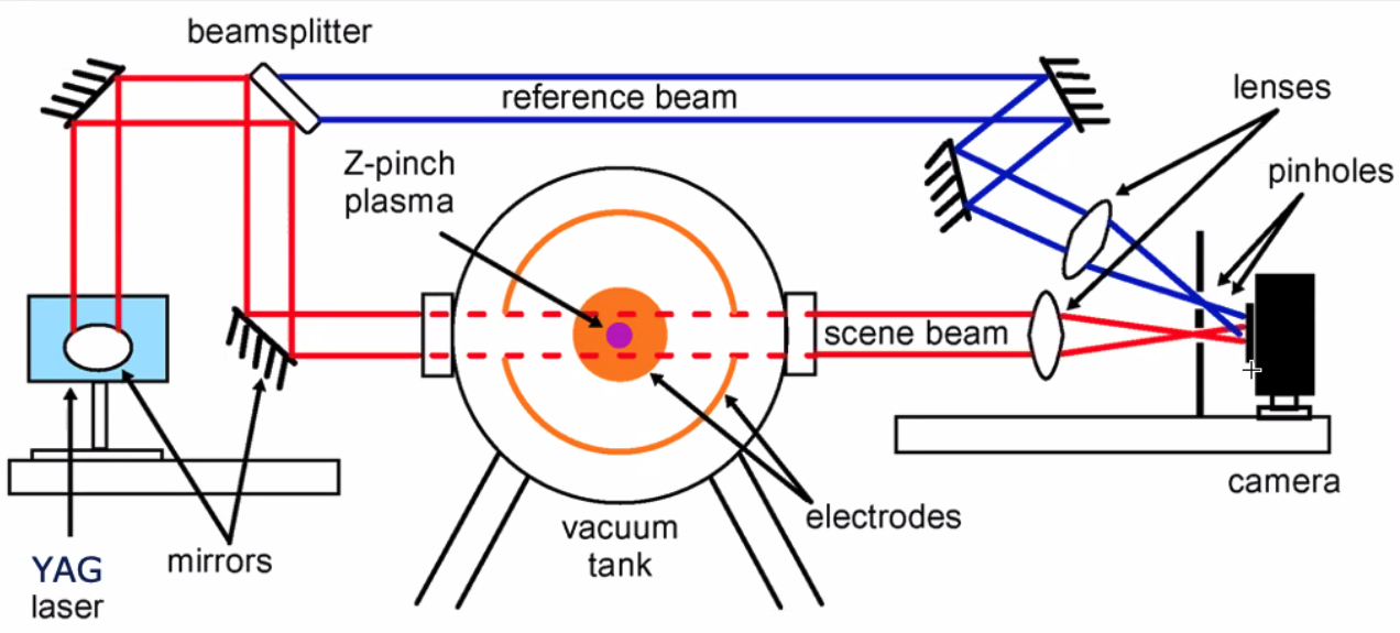
With regular layout of the Michelson interferometer, note that a portion of the source beam will pass back through the beam splitter the way it came, so we would effectively be shining the laser back into itself! That’s generally not good for the laser. Instead, we can actually use a variant called a Mach-Zedner interferometer by introducing an additional beam splitter:
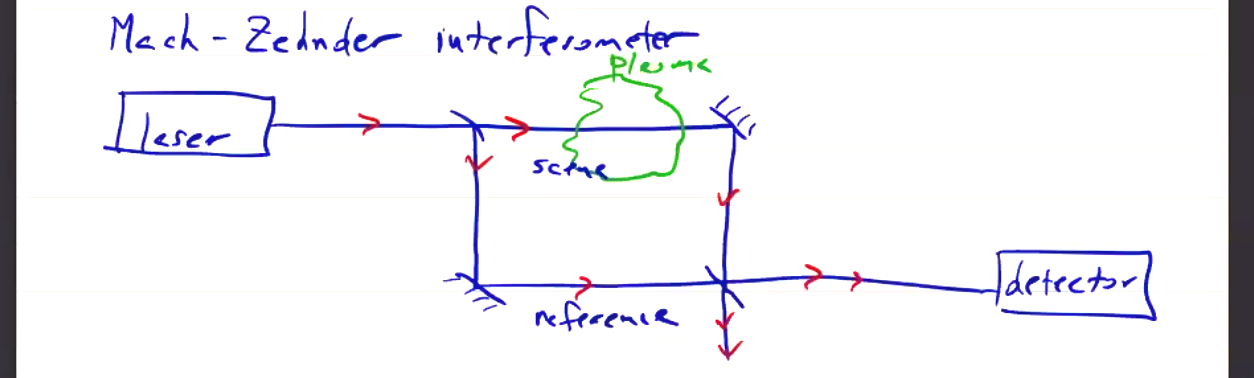
The scene beam and reference beam each reflect off their own mirror at a 45 degree angle, so they recombine into a forward beam splitter. Note that in the Mach-Zedner setup, the scene beam now only passes through the plasma once, as opposed to the Michelson interferometer where it passes through twice. So you get half the “signal” response from a Mach-Zedner.
The co-aligned, recombined beam reaches the detector, which may be a PMT or photo-optic array, but is essentially just a glorified photodiode, so what we get out is just the total incident power. How does that depend on the phase shift \( \phi \)?
\[E_{r} E^{i \omega t} \quad (\text{reference}) \\ E_{s} E^{i \omega t + \phi} \quad (\text{scene}) \\ E_t ^2 = E_r ^2 + E_s ^2 + 2 E_r E_s \cos \phi\]So the detector will measure a modulated signal oscillating about a baseline value. The temporal resolution of the detector must be good enough to detect the frequency of this modulated signal. Before we get into the measurement technique, let’s take a quick digression into the behavior of electromagnetic waves in a plasma:
Electromagnetic Waves in a Plasma#
If we consider an unmagnetized plasma. Analysis with the two-fluid plasma model provides a dispersion relation
\[\omega ^2 = c^2 k^2 + \omega_{p, e} ^2\] where \[\omega_{p, e} ^2 = \frac{e^2 n_e }{\epsilon_0 m_e}\]
This is the O-wave from the two-fluid plasma model notes. For a magnetized plasma, we arrive at the same dispersion relation for a linearly polarized electromagnetic wave with \( \vec E _\nu \parallel \vec B _0 \).
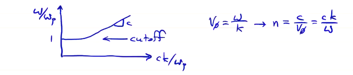
Waves with \( \omega < \omega_{p, e} \) do not propagate, so the frequency of the laser must be above the cutoff. Re-writing the dispersion relation as \( n^2 = 1 - \frac{\omega_{p, e}^2}{\omega ^2} = 1 - \frac{n_e}{n_c} \) where \( n_e \) is the electron density, and \( n_c \) is called the “cutoff density” and is equal to \( n_c = \omega^2 \frac{\epsilon_0 m_e}{e^2} \).
We can use the dispersion relation to compute the phase shift
\[\phi = \int k \dd l = \frac{\omega}{c} \int n \dd l\]A vacuum wave number \( k_0 = \omega / c \) of a laser beam and a plasma wave number \( k_p \) give
\[\Delta \phi = \int (k_p - k_0) \dd l = \int ( n - 1) \frac{\omega}{c} \dd l \\ = \frac{\omega}{c} \int \left[\left(1 - \frac{n_e}{n_c} \right)^{1/2} - 1 \right] \dd l\]If we apply an approximation \( n_e \ll n_c \), then \( \left( 1 - \frac{n_e}{n_c} \right)^{1/2} \approx 1 - \frac{1}{2} \frac{n_e}{n_c} \) and
\[\Delta \phi = \frac{1}{2} \frac{\omega}{c} \int \frac{n_e}{n_c} \dd l\]where \( \omega \) and \( n_c \) are defined entirely by the laser source. Once we have selected a laser source, the phase change is proportional to the line integral of the electron density. If we know the plasma size \( L \), we can determine the average density
\[\langle n_e \rangle = \frac{\int n_e \dd l}{L} = \frac{2 c}{\omega L} n_c \Delta \phi\]Density Profile - Multichord Interferometry#
Now, say we are interested in obtaining a density profile, not just a line-integrated average density measurement. If we add another beam splitter and direct an additional beam through a different chord in the plasma, we can obtain multiple simultaneous chord measurements. We can use these to determine the density profile. Assuming an axisymmetric \( n_e(r) \) and finite extent \( n_e = 0 \) for \( r > a \), we can define impact parameter \( y \) as the closest point of approach of the beam to the axis of symmetry:
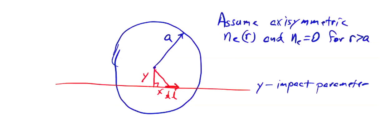
So we can measure \( F(y) \), but we really want \( n_e(r) \). We invert \( F(y) \) to give the density profile by making multiple chord measurements by the process of Abel inversion
\[n_e (r) = - \frac{1}{\pi} \int _r ^a \frac{\dd F}{\dd y} \frac{\dd y}{\sqrt{y^2 - r^2}}\]With a sufficient number of chordal measurements, we can arrive at an accurate profile \( n_e(r) \), usually. There are some pathological cases where it is difficult to determine the profile, even when it is axisymmetric. The upcoming homework is mostly about this process and these odd cases.
Phase Ambiguity#
Photodetectors, e.g. photodiodes, measure incident optical power, not just the phase shift
\[E_t ^2 = E _r ^2 + E_s ^2 + 2 E_r E_s \cos \phi\]At the points \( \phi =0, \pi, 2\pi, \ldots \) there is a phase ambiguity, because we cannot distinguish between \( \phi + \Delta \phi \) and \( \phi - \Delta \phi \). The incident optical power changes identically whether the phase increases or decreases. Adding a second interferometer with a different phase can resolve the ambiguity, since the points of ambiguity will be separated, but adding an additional interferometer is a lot of trouble. However, we can actually resolve the ambiguity with a single interferometer by modulating the phase (or frequency) of the reference beam. The scene beam of frequency \( \omega_1 ^0 \) will now interfere with the reference beam of frequency \( \omega_2 ^0 \) to create a beat frequency \( \Delta \omega^0 = \omega_2 ^0 - \omega _1 ^0 \).
Even with no plasma present, the phase will change as \( \phi(t) = \Delta \omega_0 t \). The phase will always be propagating in time. A modulated interferometer like this is a Hetrodyne interferometer. With a plasma present, the phase is further altered from the scene beam.
Modulation techniques#
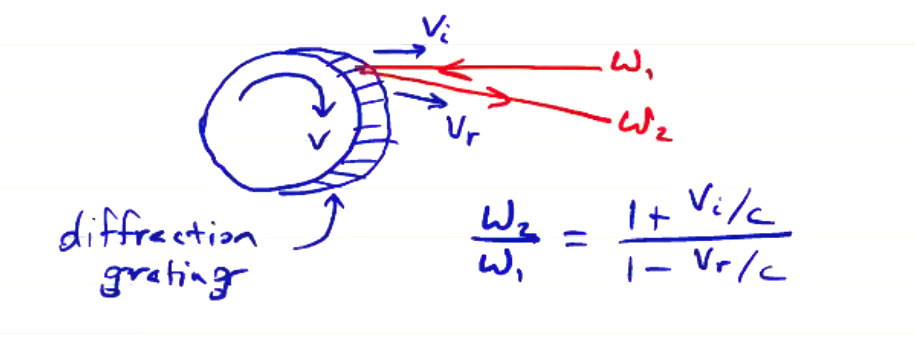
- Rotating wheel (for interferometers that use wavelengths in the far infrared). Physical wheel rotating at edge speed \( v \). Diffraction grating etched onto wheel to ensure reflection. The Doppler effect gives a frequency shift according to:
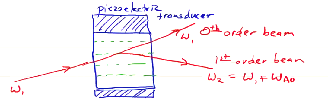
- Acousto-optic oscillators (Bragg cells). Used for lasers in the visible range (like HeNe). Composed of a crystal (quartz) attached to a vibrator/transducer, usually a piezoelectric crystal. The transducer sends compressive sound waves through the crystal to an absorber to reduce reflections. An incident laser at incident angle \( \omega_1 \) will pass through at \( \omega_1 \) (the zeroth-order beam), but there will also be a first-order Bragg reflection component which reflects off of the sound waves at frequency \( \omega_2 = \omega_1 \pm \omega_{ao} \) where \( \omega_{ao} \) is the frequency of the acousto-optic oscillator.
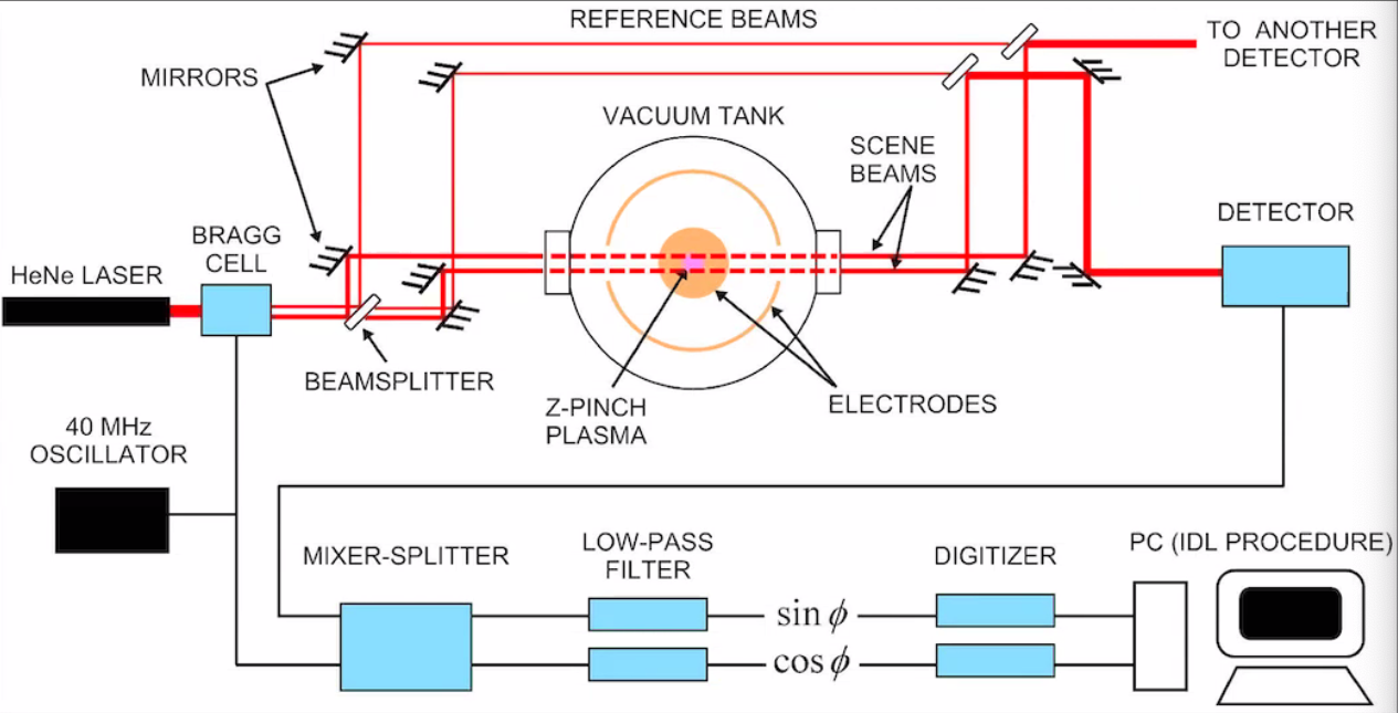
The detector signal \( f(t) \) is combined with the local oscillator \( \omega_{ao} \) to output \( \sin (\Delta \phi) \) and \( \cos (\Delta \phi) \) in a mixer-splitter quadrature detector. Whenever setting up these interferometers, it is very useful to plot \( \sin(\Delta \phi) \) and \( \cos (\Delta \phi) \) to produce a circle called a Lissajous figure. A very well-aligned interferometer will have a very circular Lissajous figure with large radius, so it is a useful reference when aligning the interferometer.
Density Imaging#
As the plasma has an index of refraction change, the scene beam can refract (and change direction) as is passes through the plasma. This can cause the scene beam to become misaligned from the reference beam. This particularly happens when you go through a density gradient. When the wavefronts of the scene and reference beams are no longer co-planar, a new interference pattern appears at the detector which complicates the signal, and can even eliminate any modulation. We can actually take advantage of this problem if we have a sufficiently large beam:
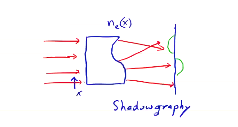
Intentional misalignment of an expanded beam produces an interference pattern that we can image. The signal measured at the detector now corresponds with the second derivative of the density gradient.
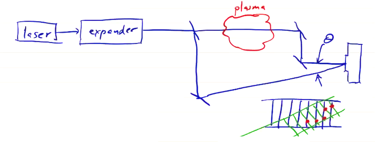
The detector will measure an interference pattern of horizontal fringes, spaced depending on the laser wavelength and \( \theta \). The fringe spacing can be small, depending on the wavelength and misalignment. In the before-times, you would generally use holographic glass plates at the detector, but nowadays consumer-grade SLR cameras have sufficient resolution to detect.
With plasma present, the fringes are distorted. Encoded in the fringe pattern is the phase difference between the scene and reference beams. The image with plasma will contain deflections in the fringes. The deflection away from original horizontal fringe pattern gives \( \Delta \phi \).
Faraday Rotation#
The polarization angle of the laser changes as a result of the Faraday effect. The effect can be used to measure the magnetic field.
TODO: Fill in section on March 4 during lecture on pulsed polarimetry.